Skateboard Remote Control
2016
This was the first PCB I ever designed. At the time I was interested in building an electric skateboard, and I wanted to make my own wireless skateboard controller.
Idea
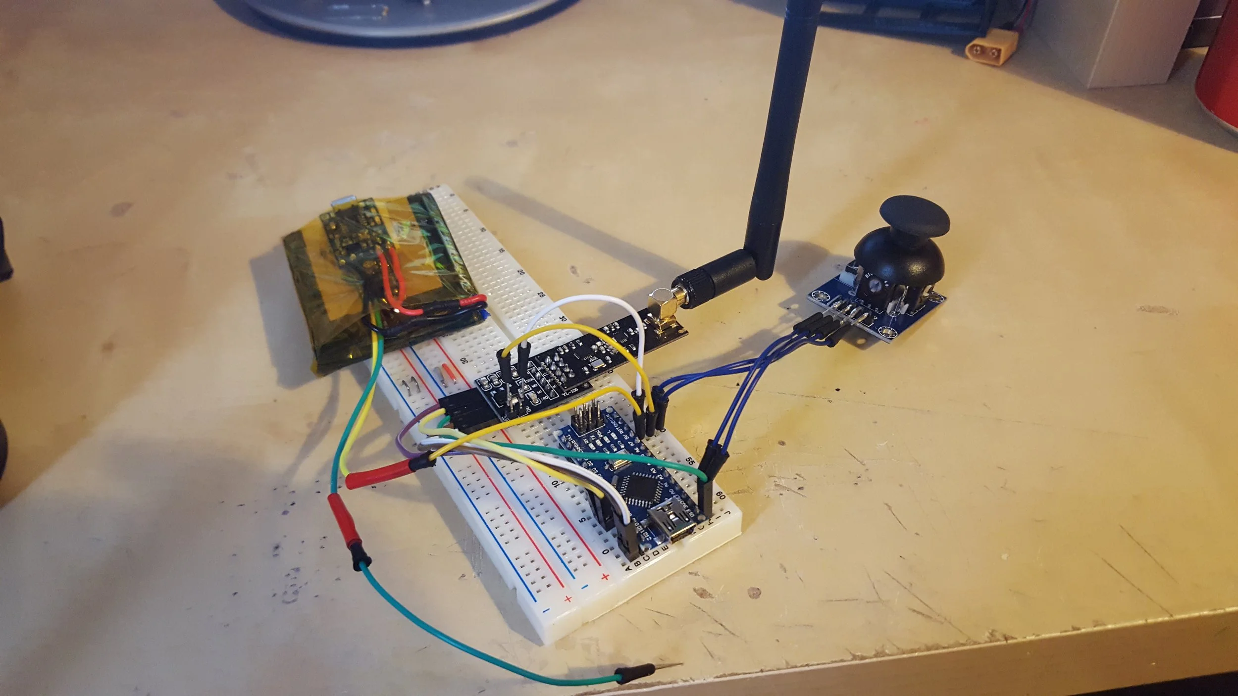
The idea for the controller was to have a handheld remote with a slider to control the skateboard speed. I decided it would also be a good idea to add a small screen to the controller so you could view the battery level of the skateboard and the controller.
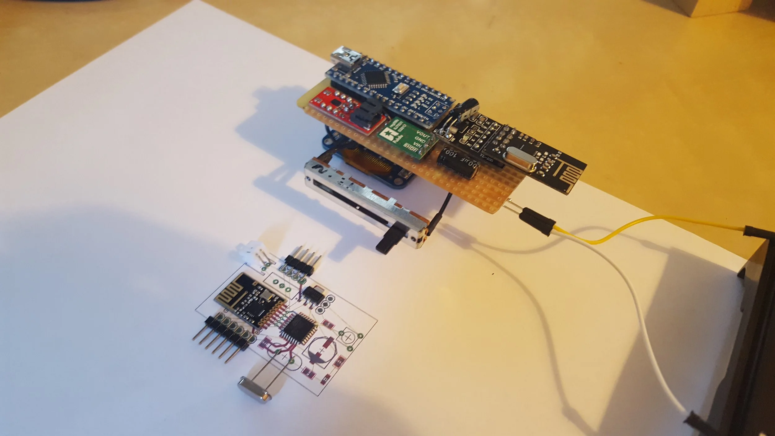
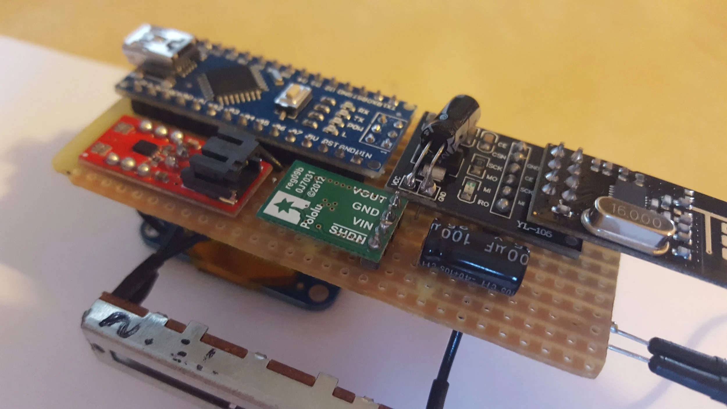
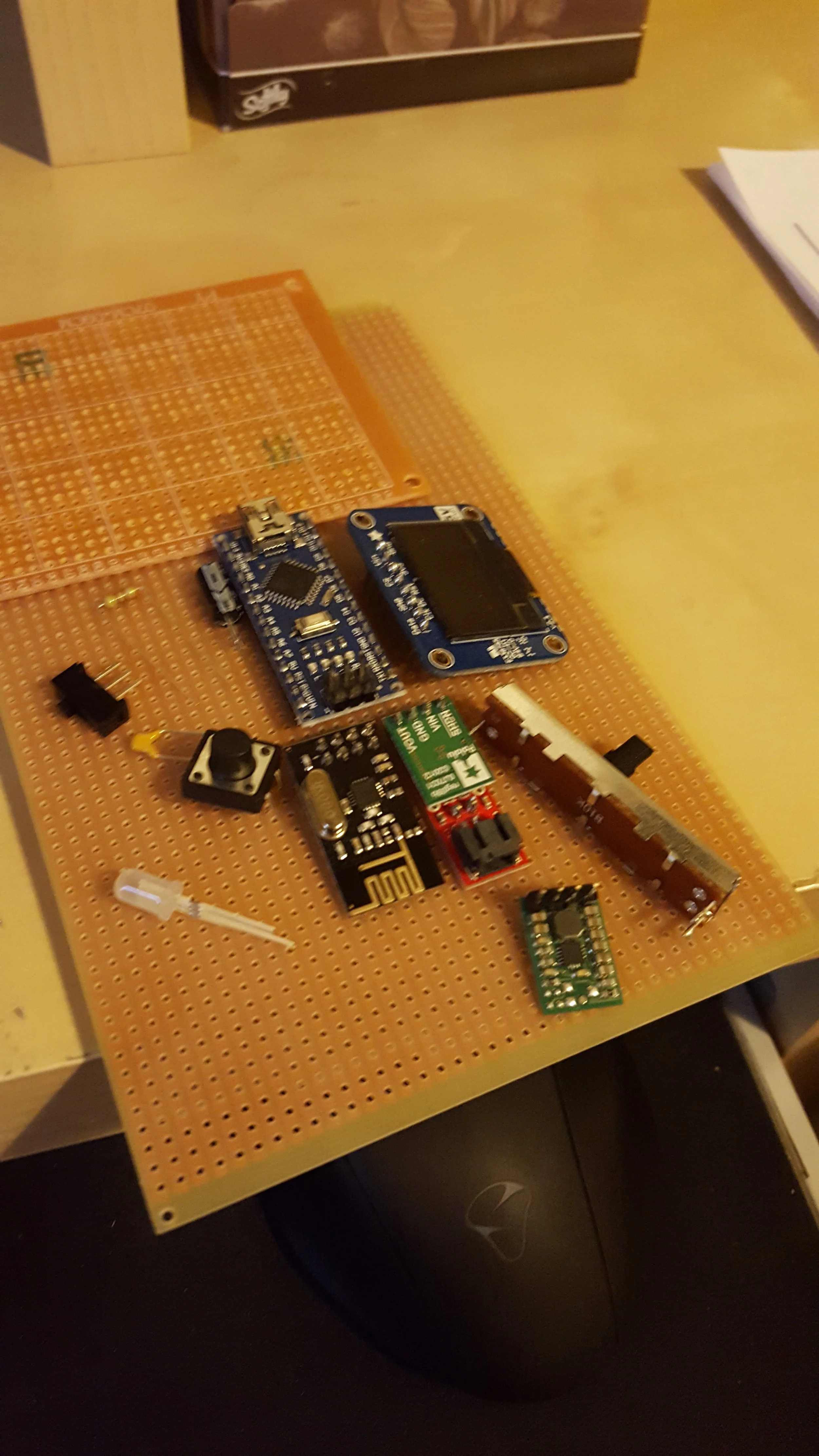
To start the project, I prototyped the parts on a normal breadboard and then soldered them to a solderable breadboard. The controller used an Arduino nano, OLED display, DC-DC converter, linear potentiometer, and a NRF24L01 2.4GHz transceiver.
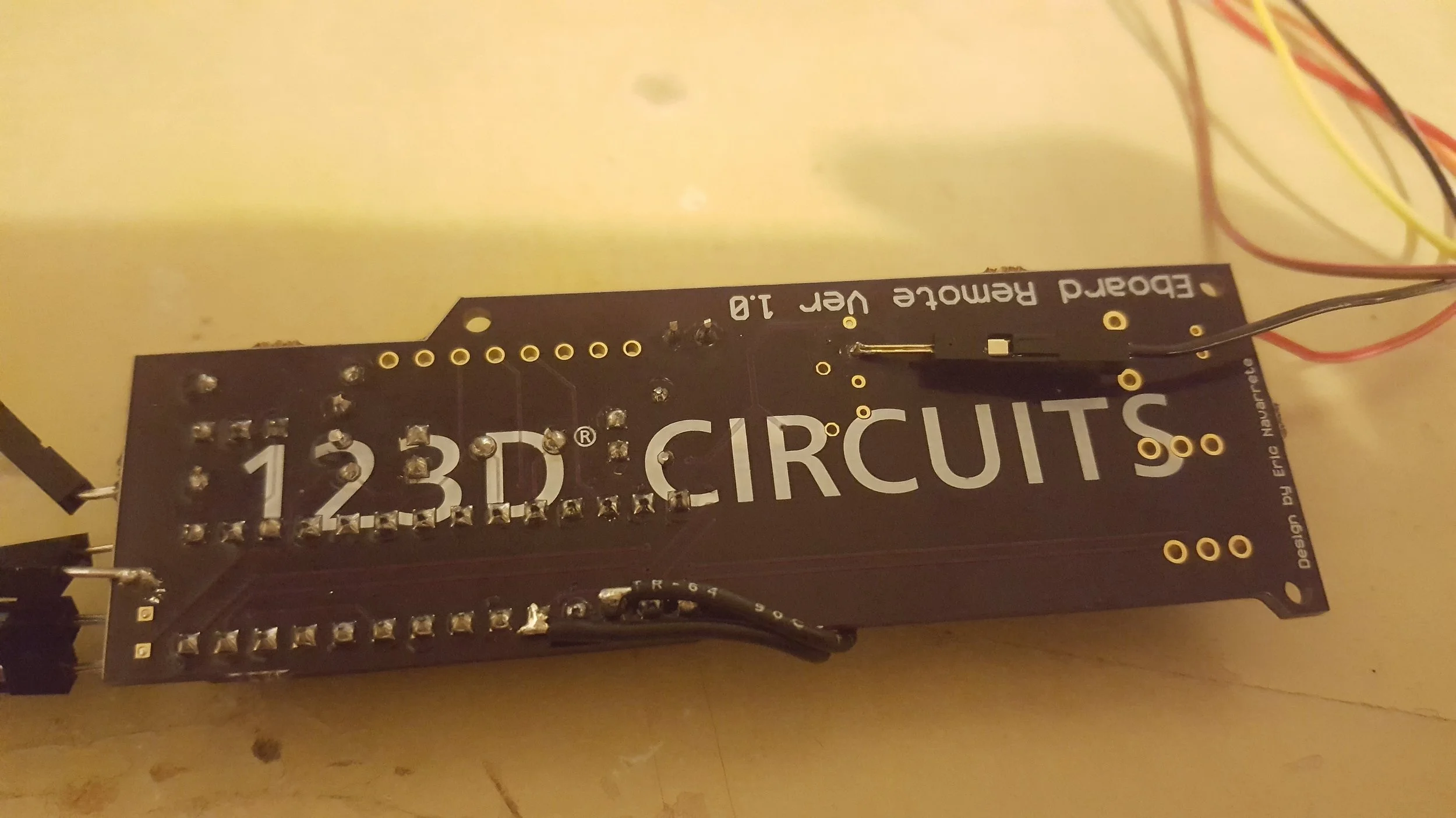
PCB
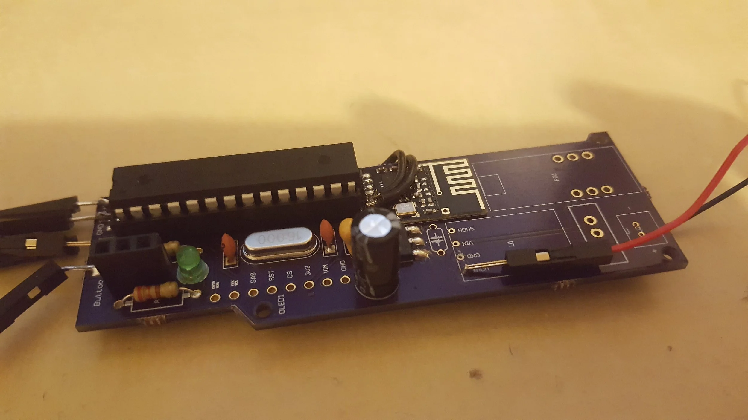
After I got the circuit working on a breadboard I discovered an online PCB design tool called 123D circuits. It seemed like one of the easiest design tools at the time so I used it to create the PCB. The PCB design is horrible as you might expect since it is the first PCB I ever designed with zero knowledge on the subject. There were many errors in the design, but I did get it partially working with some bodge wires.
Future versions
After the first PCB design, my interest in electronics and PCBs grew, so I started using a better EDA tool made by CadSoft called Eagle. I started creating a new version of the PCB which was significantly smaller than the first version. I never ordered the second PCB since the other parts of the skateboard project slowed. The motor, and battery pack for the skateboard were too expensive for me at the time so I decided to work on other more affordable projects.