I have liked the idea of making my own watch for quite a few years. The idea of wearing my own custom designed hardware when leaving the house seems cool to me. There is also the added benefit that if | ever want to show off my electronics skills to someone, | would have the watch on hand to show off
E-Ink Watch
2018
Design goals
The goal of this watch project was to test/play with a variety of ICs that interested me and also hopefully get a somewhat practical watch out of it at the end. I did not want to try to make a “smart” watch since it is possible to go and buy a very capable smart watch at any price point now. I also did not want to add the burden of learning how to develop a phone app and device firmware to communicate over Bluetooth. The watch is a stand-alone unit which doesn’t rely on any phone connection, but has a few cool sensors built in and can tell the time. Ideally the watch should have very good battery life and be relatively small since I have very skinny wrists.
V1
V1 was not overly ambitious. I decided to use a SAMD21 microcontroller since I had experience with it previously and it has enough performance for this humble watch. Another big consideration was the support available for the SAMD21 since it is the MCU the Arduino Zero uses. This means it is very easy to program with the Arduino IDE, which was the only embedded IDE I had experience with at the time.
Display
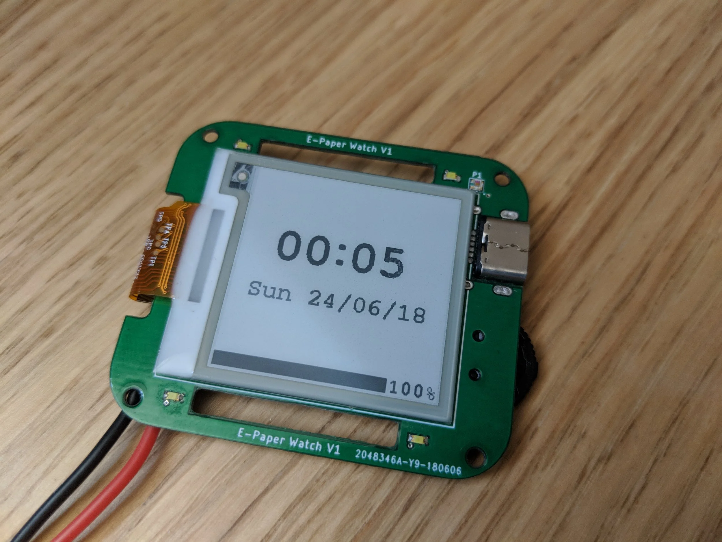
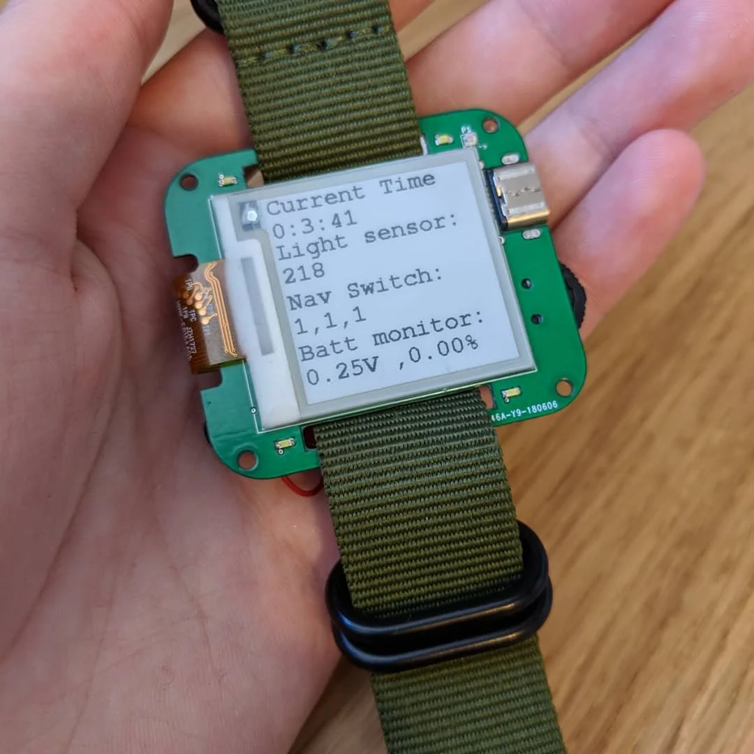
Choosing the display is a very important design consideration since it will have a large impact on battery life, user experience, and determine the performance requirements of the MCU. I considered using a small OLED display, but in the end decided on a 1.54” E-Ink display. The E-Ink display only needs power when updating which means the time can always be displayed while also having very good battery life. I based the display driving circuity off of commonly available breakout boards from suppliers like Adafruit and the display driver data sheet.
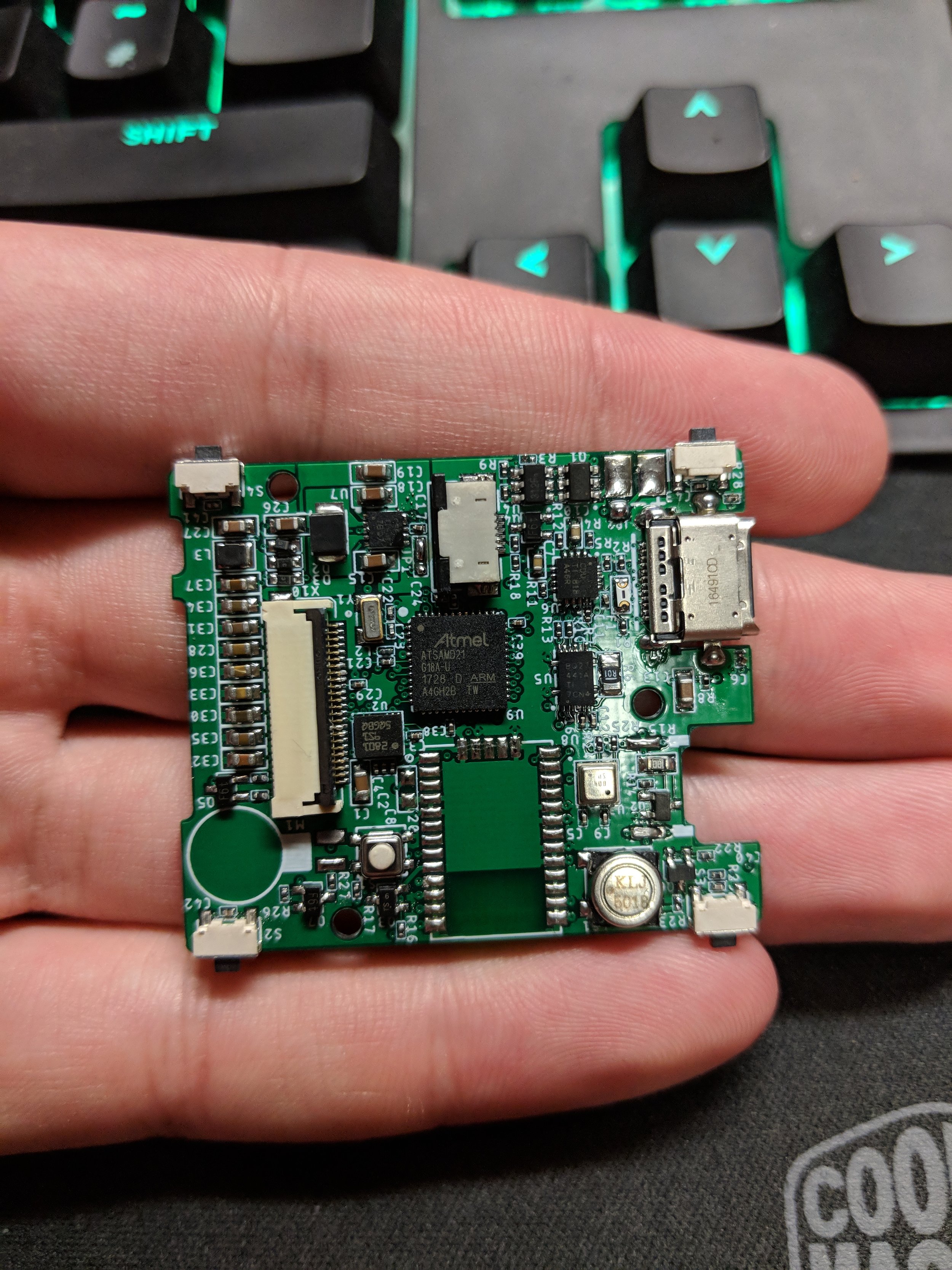
General circuit
The watch circuit was relatively simple. It featured battery protection, battery charging, battery fuel gauge monitoring, native USB C for programming, a buck-boost converter for system power, and a boost converter for the display. It also has a piezo buzzer, navigation switch, ambient light sensor, and LED’s to provide a front light for the display.
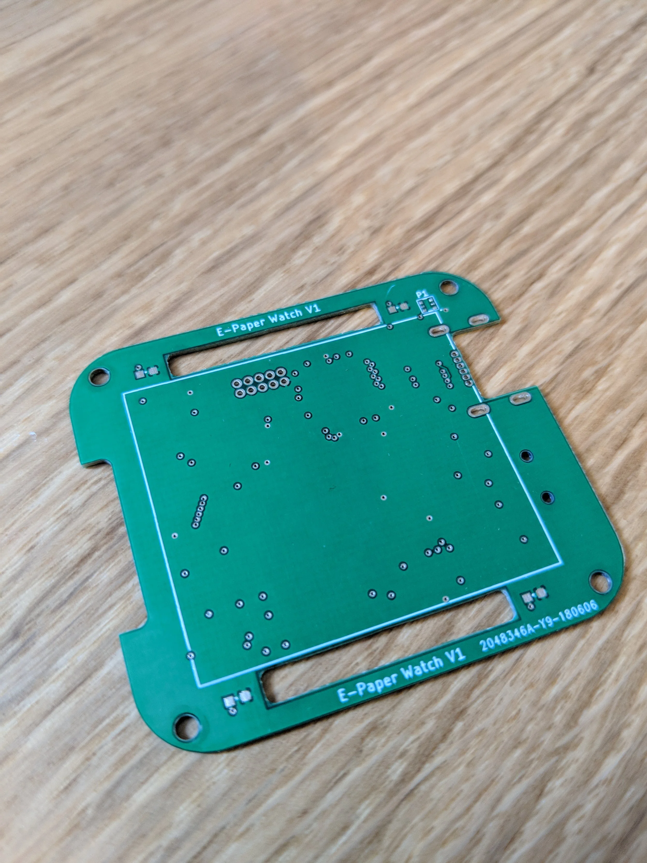
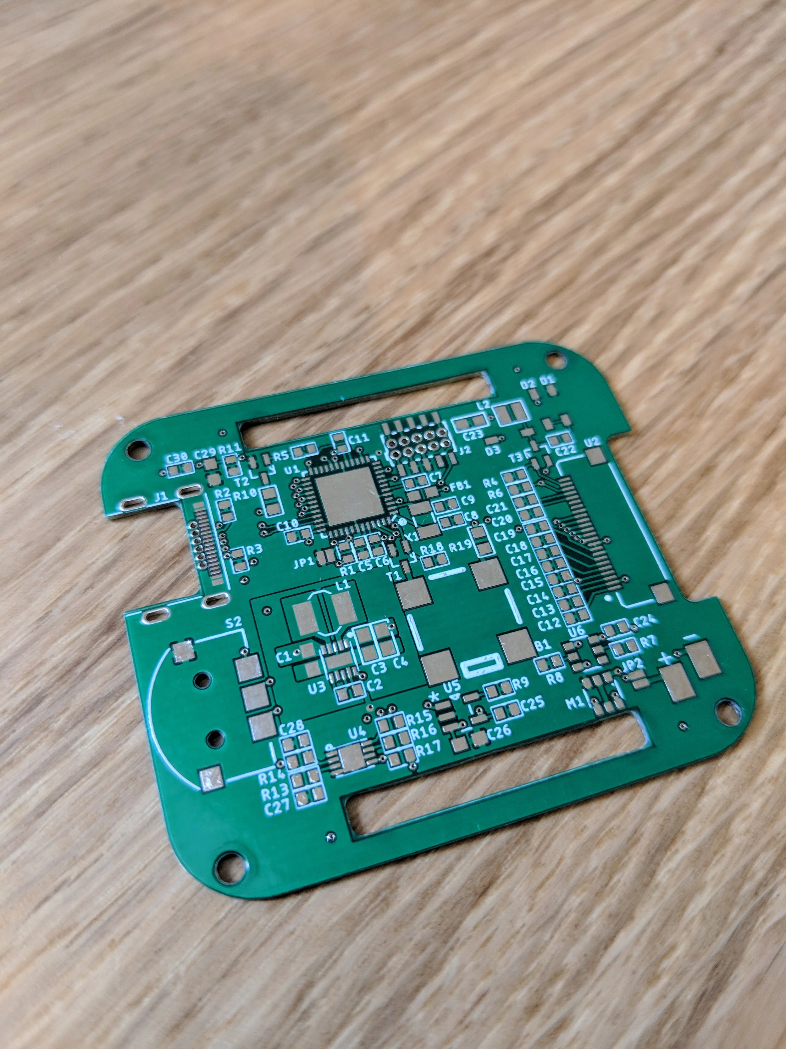
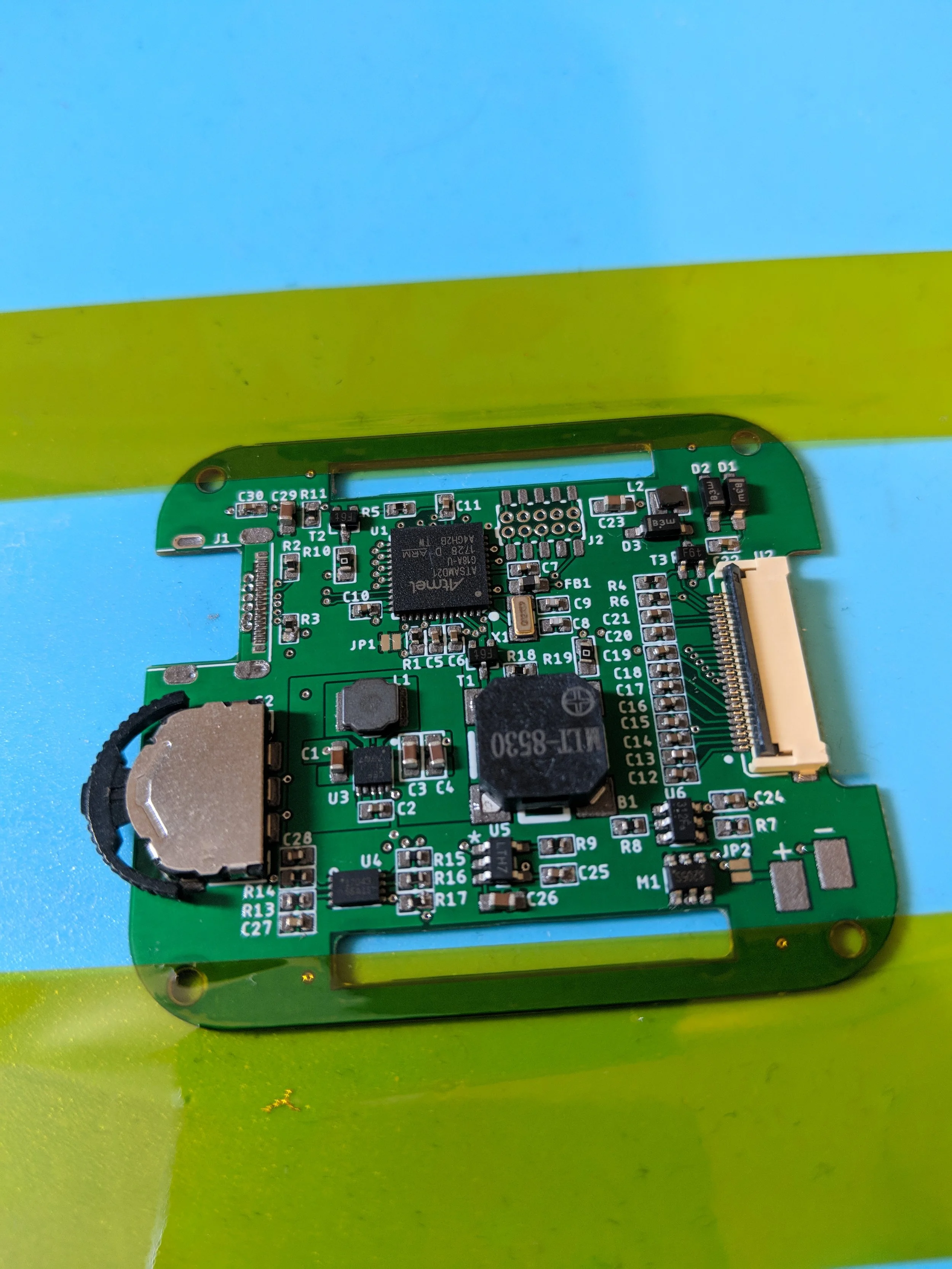
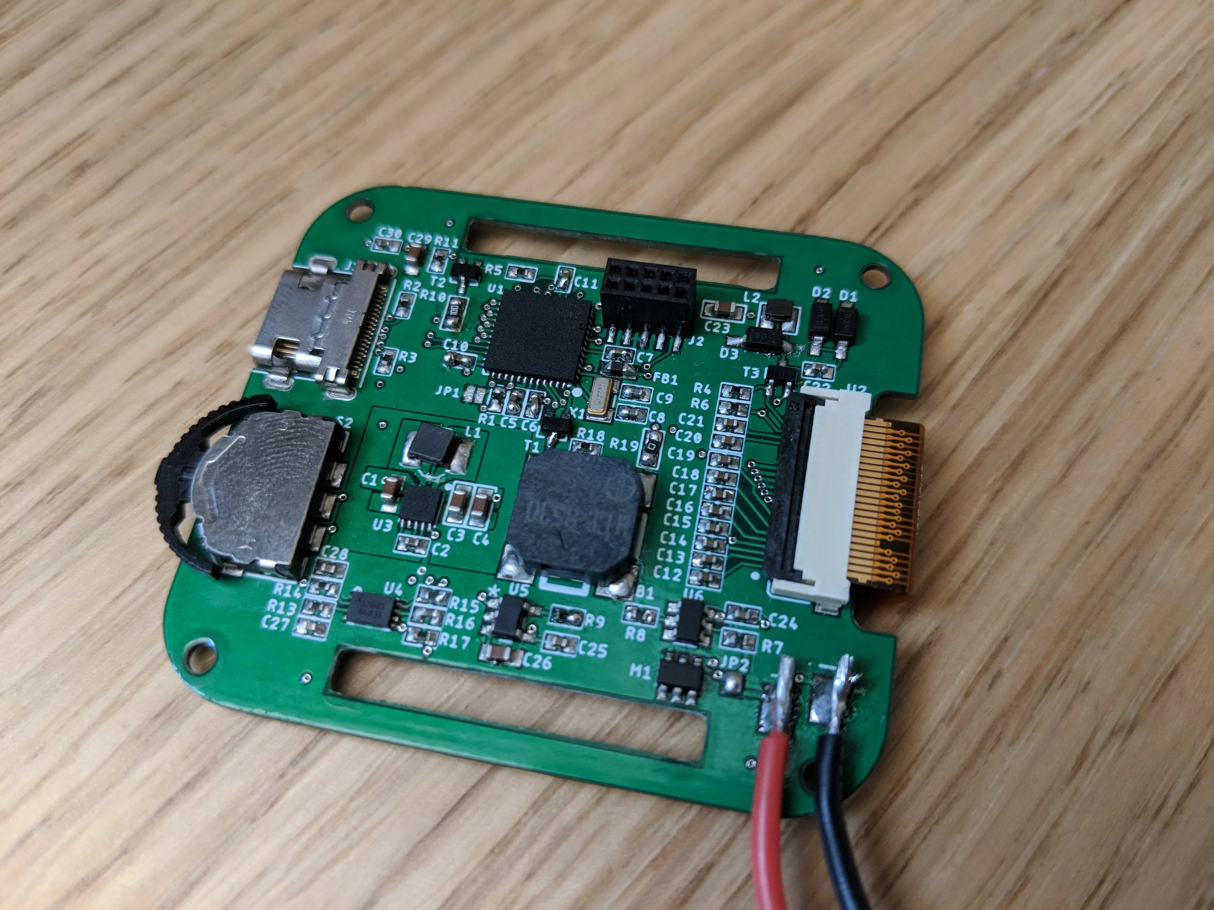
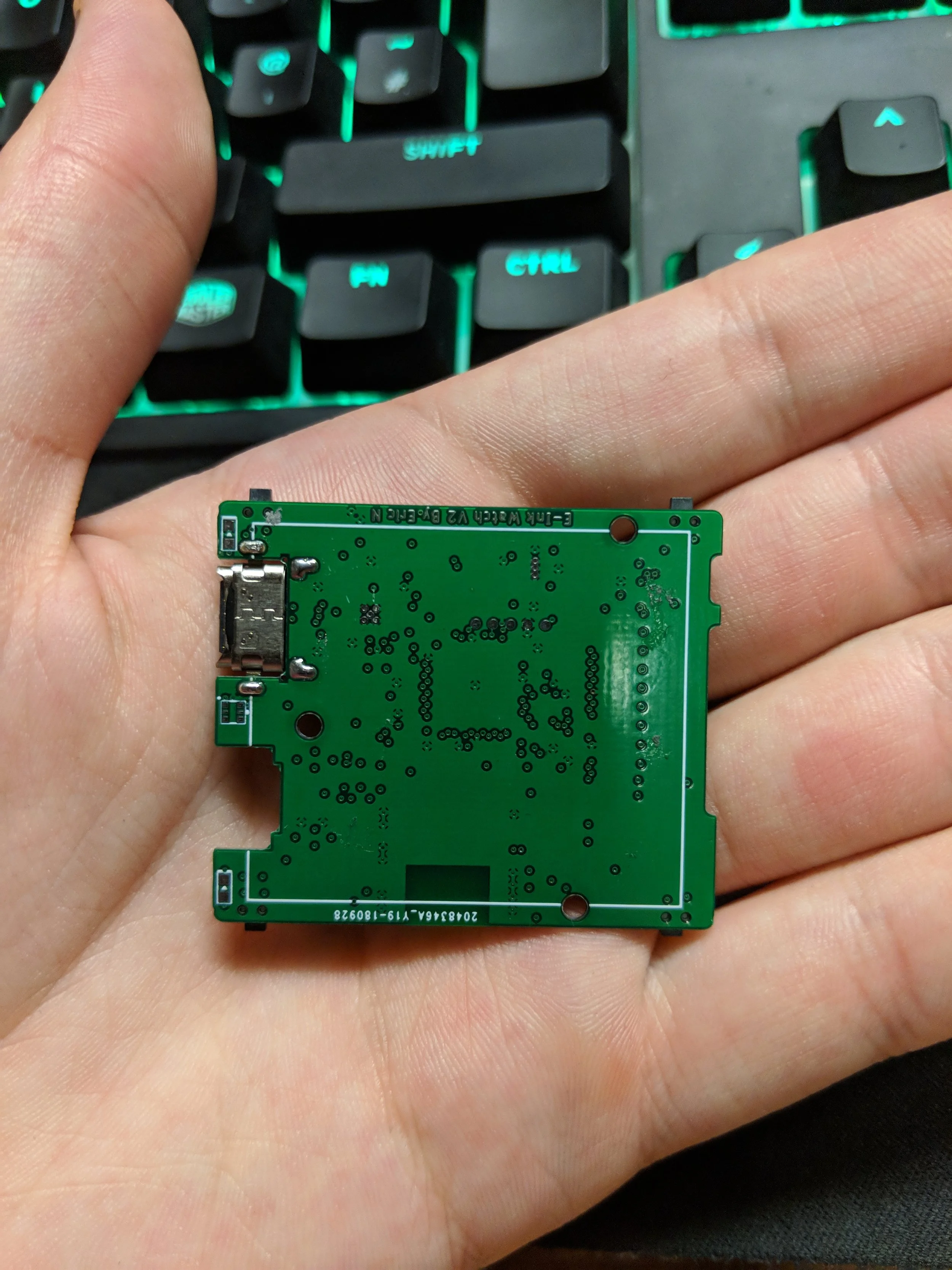
PCB
The PCB design features a mid mount USB C receptacle to reduce the overall thickness of the board. I also had the idea of adding slots to the PCB for the watch strap to go through. The slots were an interesting idea, but they were dropped on the next version due to fears of the PCB breaking or flexing from the force of the strap. Somewhat surprisingly, the PCB worked on the first try without any modifications. Looking back, I can see some things I would have done differently since my PCB layout skills have advanced a lot since this project. For example, the buck boost regulator has an isolated ground pour which is a bad idea in this case, and the RTC crystal is not layed out very well.
V2
After the success of V1, I wanted to add more features to make the watch more fun and try out some new sensors.
I added the following:
Display with integrated front light
LSM9DS1 9 DOF accelerometer, gyroscope, and magnetometer
BME680, temperature, humidity, pressure and gas Sensor
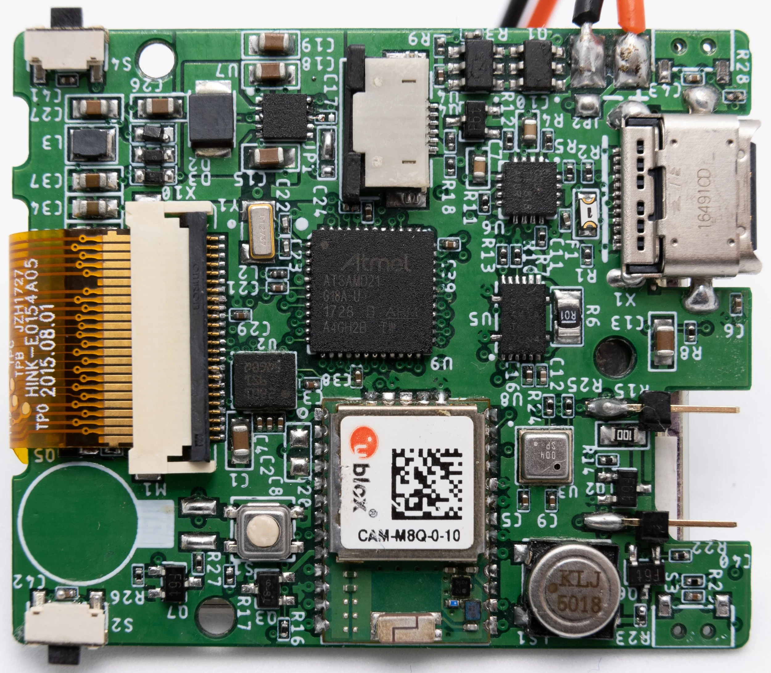
CAM-M8Q GNSS module with integrated chip antenna
High power LED
Vibration motor
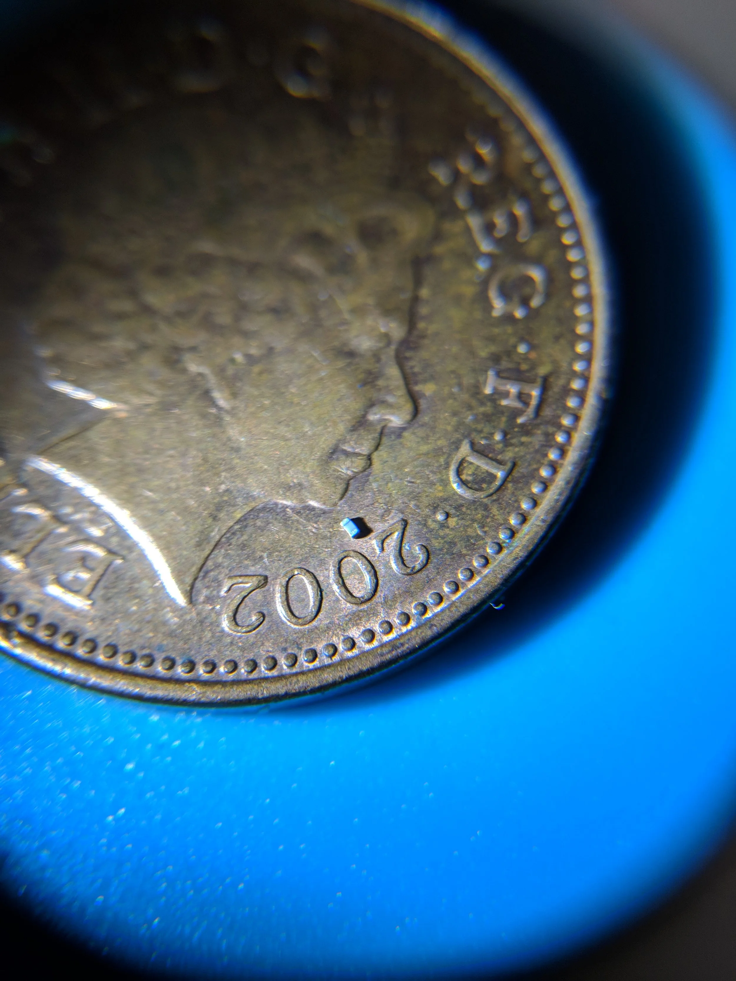
Since the component count greatly increased with V2, I moved to using some 0201 size passives in order to keep a similar PCB size. Hand placing 0201 components is time consuming and difficult, but as long as you use a good pair of fine tweezers it is very doable.
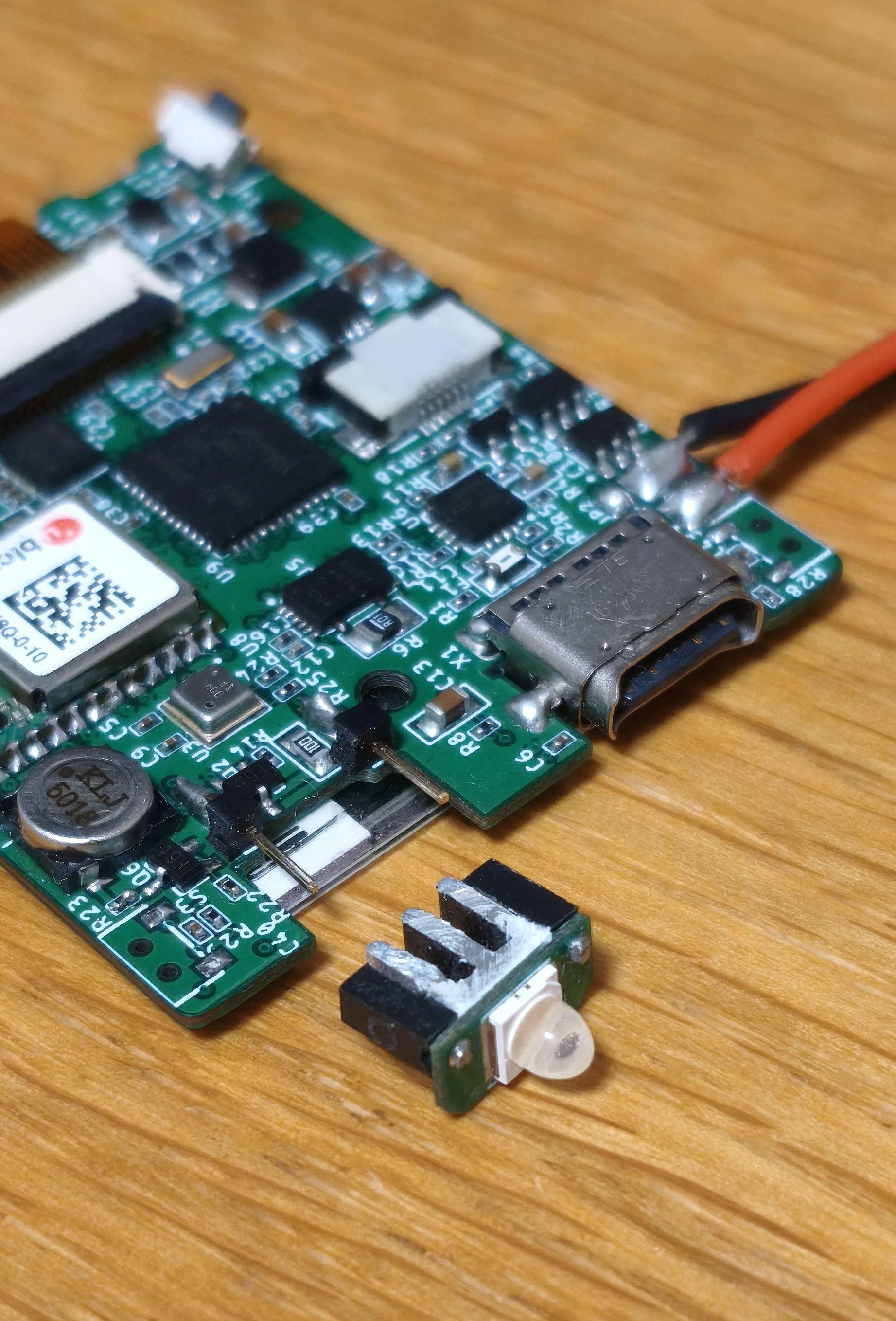
High Power LED
The idea behind adding a high power LED was that the watch could be used as a torch when walking at night or in emergencies. To orient the SMD LED in the correct orientation, I mounted it to a second 9x4.5mm PCB. The LED PCB is attached to the main PCB with two pin connections and there is a small heat sink thermally epoxied to the LED PCB. The LED model was selected because it has an integrated lens to reduce the light spread without the need of any external optics.
Other features
The other added hardware features mostly worked well. The GNSS module did not have very good satellite reception due to the small ground plane of the PCB. In this case a custom tuned antenna design would be necessary to improve performance.
Conclusion
You might be wondering why I haven’t talked about the watch case or the software. That is because after testing V2, the project stagnated. I think the main reason I didn’t completely finish the project was due to the fact I bit off more than I could chew with regards to software. To get all of the features working together and to display a nice user interface is not an easy task. At the time of this project, I was limited to using Arduino libraries to get sensors and peripherals working, which limited many aspects of the code. I became overwhelmed with the prospect of getting everything working together and also had other project ideas, which meant this project was left unfinished.
This project is a good example of feature creep. Had I kept things simpler, I likely would not have been so overwhelmed and I would have a finished product at the end. This taught me a valuable lesson for future projects, although it is still easy to fall victim to feature creep even when you realise it’s happening.
With my much improved software and hardware experience a few years after leaving this project, I am getting ready to return to it and complete it. I still want to have a watch to show off to people, so I will return in the future to make a third and final version.