This project came about from the need to replace a broken controller for a pair of heated motorcycle gloves. The controller device needs to regulate the power going to the gloves, and have a user interface for the wearer to select the heating level. The driver will be powered by lithium polymer batteries, so it should also have a low voltage cutoff so that it does not over discharge the batteries.
Heated glove controller
2019
MCU
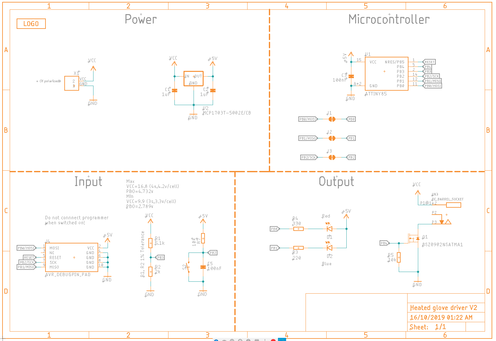
For this project I wanted to practice programming a microcontroller without the help of the Arduino environment. I chose to use the AtTiny 85 MCU since it is used in many projects in the maker community. It is also low cost and has enough IO for this project.
Mosfet
I also needed to choose a mosfet with a low on resistance to ensure good efficiency of the system. The gate charge of the mosfet also must be considered since the gate will be driven directly from an IO pin. The gate charge should not be too high to avoid exceeding the MCU’s pin output current when switching. I spent time on the component distributor’s website using the parametric search feature to find a suitable mosfet.
Control
To control the power to the gloves I used pulse width modulation from the mcu to an N channel mosfet. By toggling the mosfet on and off in quick succession, and varying the on/off pulse ratio, the temperature of the gloves can be controlled. There is no temperature sensor in the gloves, so this is a open-loop system, but that is fine since the temperature doesn’t needs to be a precise value.
Battery Protection
The driver also needs to shut down when the battery voltage gets low to prevent over discharge. To achieve this I used the internal voltage reference of the AtTiny and a voltage divider. The centre of the voltage divider was connected to an input pin with ADC capabilities. By measuring the ADC value the battery voltage can be compared against the programmed cutoff voltage.
Interface
A push button switch was used to control the heat setting of the gloves. Using a large single button allows modes to be changed even while wearing bulky gloves. I decided to have 3 heat levels the user could select. There is also two LEDs, one red, one blue, both connected to IO of the mcu. These are used to indicate the current status of the device to the user.
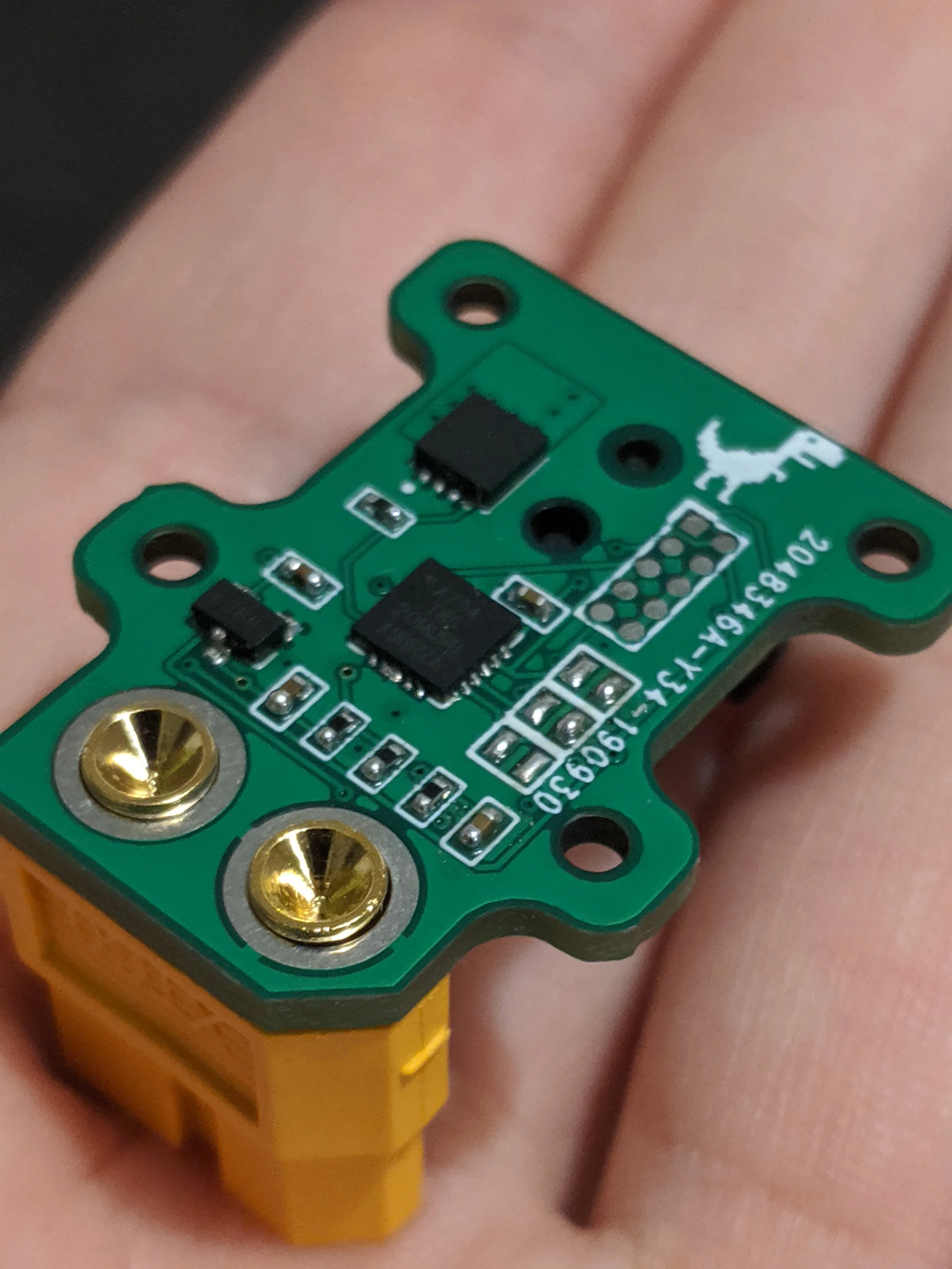
Assembly
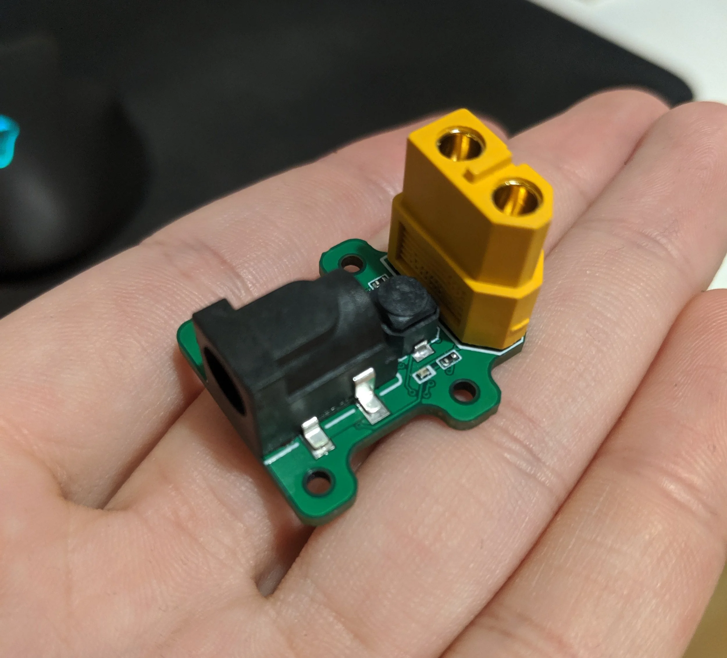
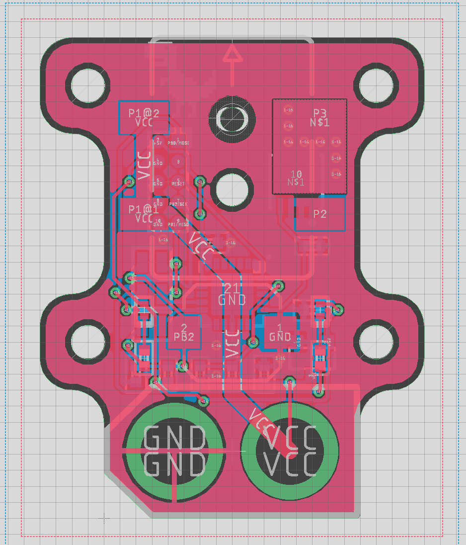
The PCB and stencil were ordered from the fabricator in China after the layout was complete. Paste was applied with the stencil and the SMD components were placed in order of ascending size. The soldering was done using an infrared pre-heater and hot air station. Next, I soldered the components on the top side using a soldering iron, checking for any errors and shorts once complete.
Programming
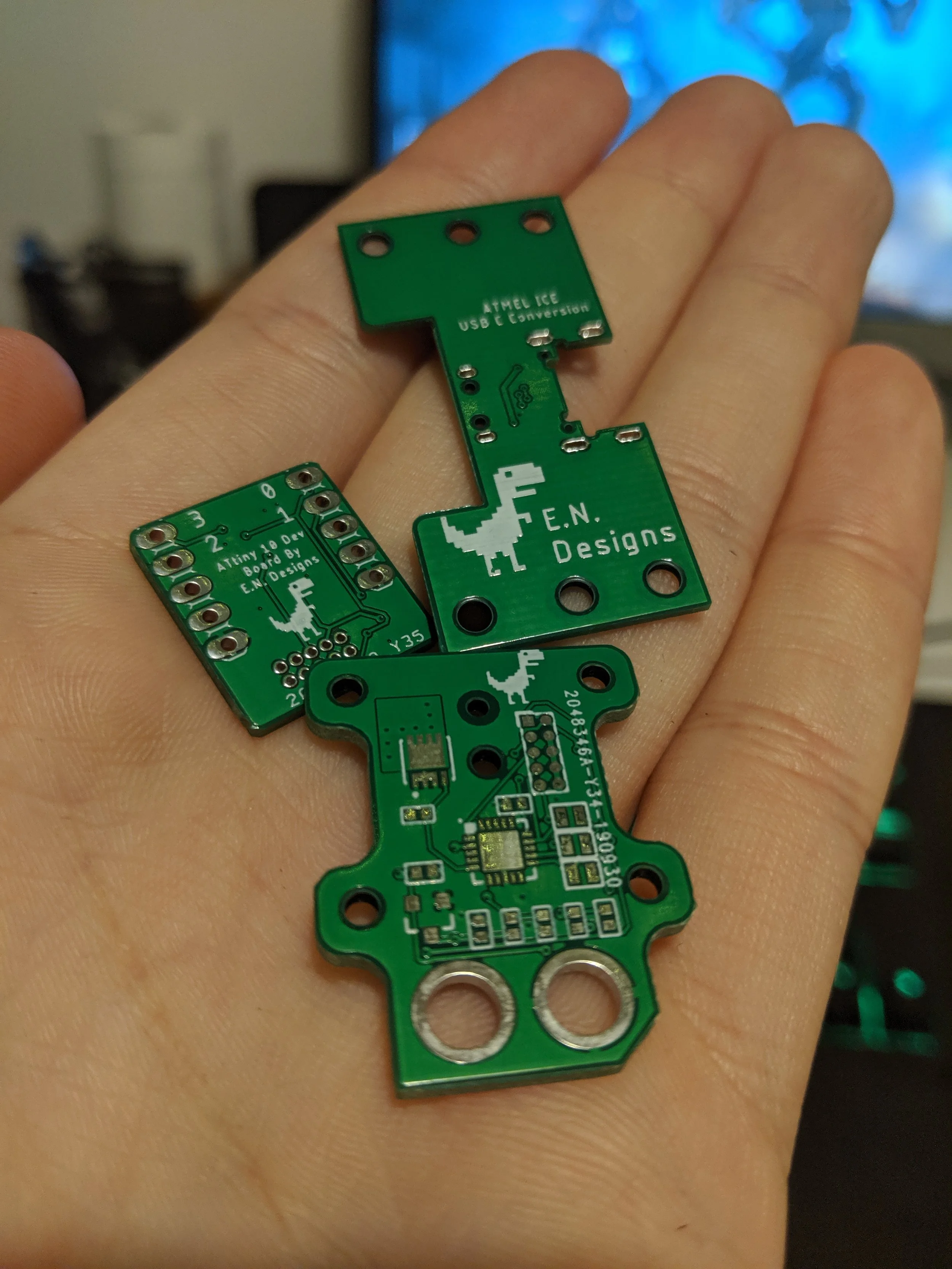
To keep the board as compact as possible, I opted to use pogo pins to program the MCU. I wired a custom cable for the Atmel ICE programmer to 10 pogo pins which match the programming pads on the PCB. To program the MCU I just needed to hold the pogo pins to the copper pads while uploading the code.
The software was developed in Atmel Studio, and uploaded using the programmer. I had to configure the ADC and voltage reference to implement the low battery voltage cutoff. I also configured one of the built in timers to generate the PWM signal for the mosfet as well as configured the digital IO for the button and LEDs.
Conclusion
After a while developing the software the glove controller worked as intended. There are a number of improvements that could be made such as re arranging the layout for the large connectors to allow easier access to the button, as well as improving the software to be more optimised. This project was a good experience learning to program in Atmel studio instead of the Arduino IDE. To further improve my low level programming skills in future I plan to do another project with more sophisticated software requirements.