This project was a test to learn about how to use high power LEDs. I was considering adding a bright LED to my smart watch project, so I produced a board to test the power requirements, and how to manage the heat generated.
High power LED driver
2020
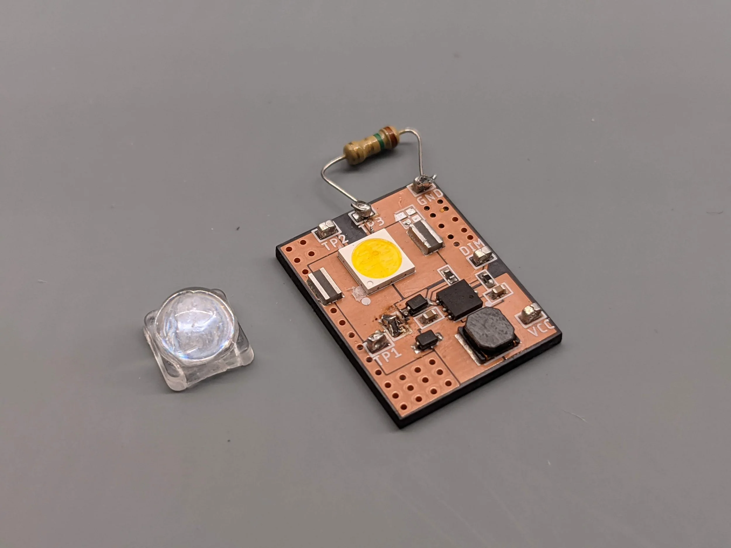
This project was relatively simple to complete. I decided to use the LM3410 constant current boost and SEPIC LED driver from Texas Instruments. It is a small, highly integrated, affordable IC that can be configured to drive a single or string of LEDs. Most time on this project was spent reading the IC’s datasheet. The component values for my particular LED were calculated with the help of the datasheet. I chose components to minimise the size of the driver as much as possible because I plan to use this IC with the same components in other wearable projects where space is very restricted.
A key part of this test PCB was to see how well thermal jumpers worked for this application. A thermal jumper is a component designed to have a high thermal conductivity, but poor electrical conductivity. The LED I used only had connections for the Anode and cathode, but it needs to dissipate over 2 watts when at full power. The thermal jumpers allow the anode and cathode of the LED to be thermally connected to the ground plane of the PCB for heat dissipation which helps save space.
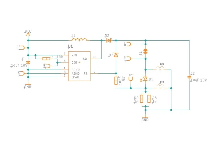
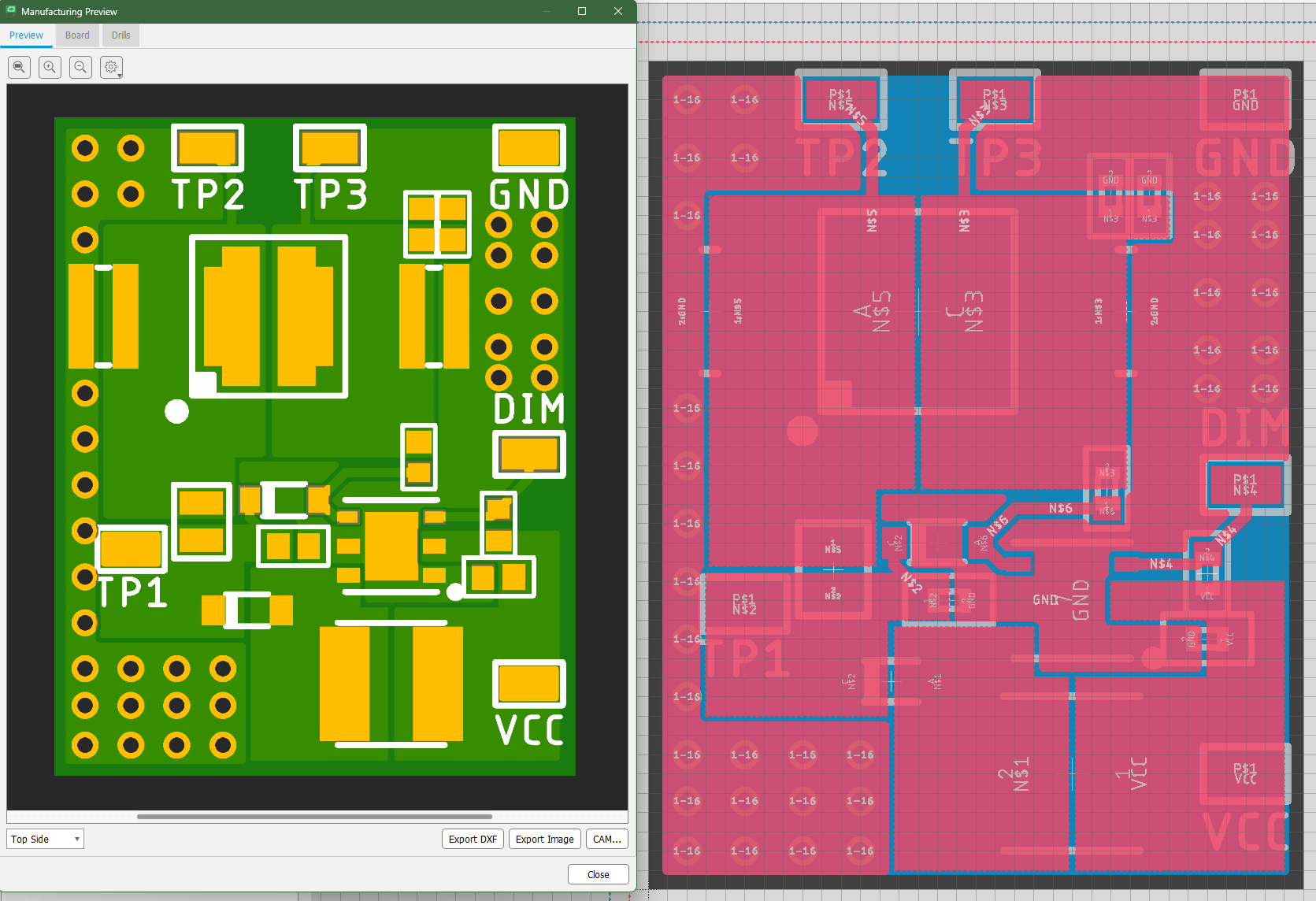
I made sure to include many test points when designing the board to allow for easy measurement of values like current and voltage through the LED. Also, since the LM3410 is a switching regulator, special care must be taken when doing the PCB layout to keep the impedances low between the IC and the other components such as the inductor, diodes, and LED.
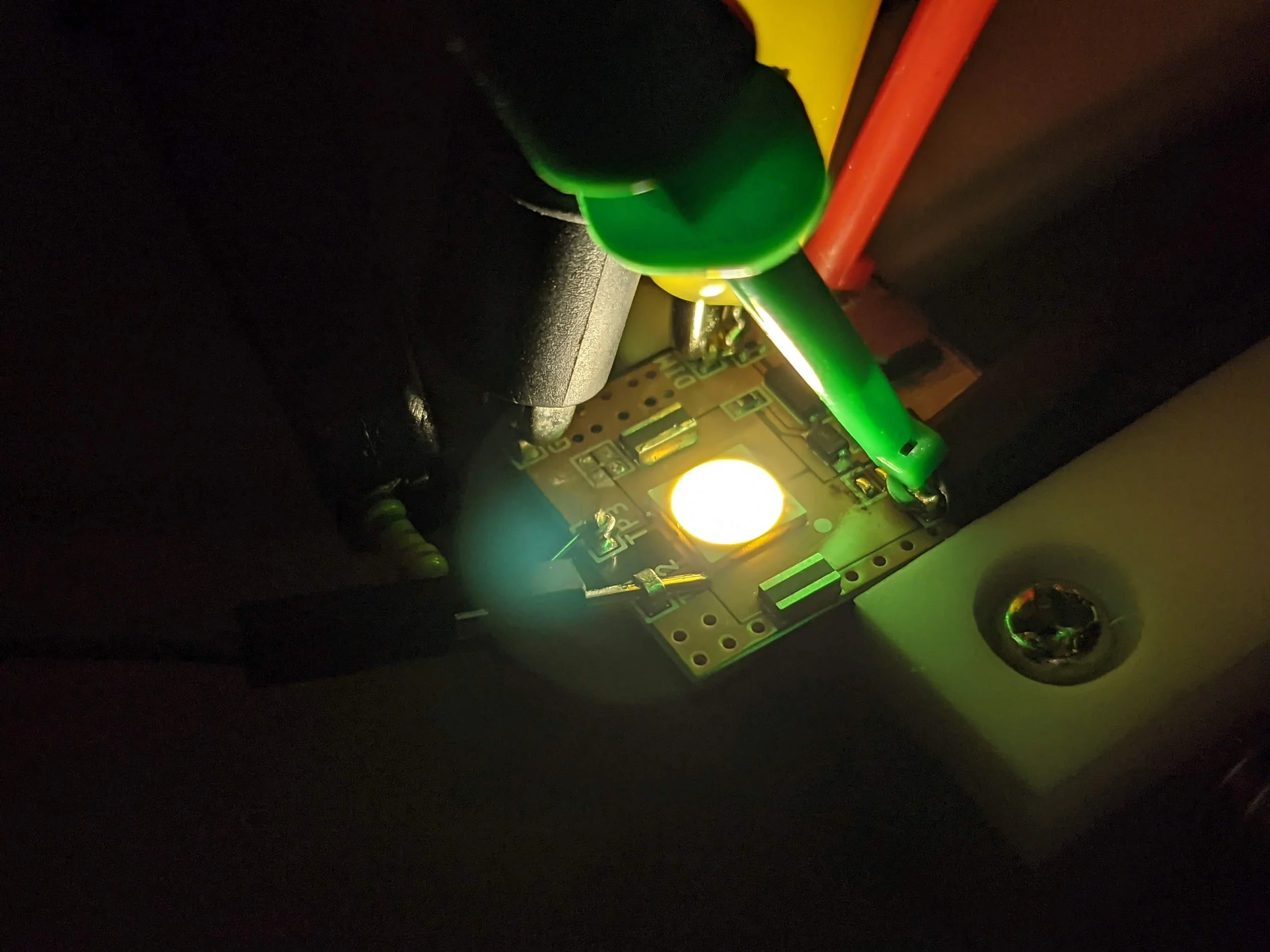
The completed board worked well, although it couldn’t handle maximum LED power without attaching a small heatsink to the back of the PCB. The project was a good learning experience to understand thermal management of components and best practices for layout of switching regulators.